We know that CAN Communication is the most prominent communication protocol in the automotive industry. In a CAN Network, there are multiple ECUs talking to each other. Each ECU communicates with another ECU via a CAN message. Since there are multiple ECUs on the same network, it is essential that we as network engineers define the source and destination of a particular message. In this article, I will walk you through
What is a CAN DBC?
What are the different contents of a CAN DBC?
How to create one?
What is a CAN DBC?
A DBC file (in CAN communication) is a text based CAN data description file containing all the necessary information about a CAN network. DBC stands for Data Base Container. This file format was introduced by Vector Informatik GmbH. These files are suffixed with a .dbc extension. Since these are text based files, they can be easily opened and read/analyzed using a simple Text Editor like NotePad++.
The following are the uses of a CAN DBC file:
It is used to maintain all the network information.
It is used to exchange the Communication data between OEM and Suppliers.
It is also used for Communication Stack Configuration in tools like Vector DaVinci Configurator/EB Tresos or other configuration tools.
It is also used in verification and validation activities using Vector Canoe or other relevant tools.
What are the contents of a typical DBC file?
A CAN DBC typically contains the following information:
The Protocol type, whether it is CAN 2.0 or CAN FD.
The network and the participating nodes/ECUs.
The Baud rate used for the network.
Messages and their respective source and destination nodes.
Messages and the corresponding signals.
Individual message and Signal properties.
Next we will see how we can create a CAN DBC.
How to create a CAN DBC file?
Previously we saw that, DBC files are text based and are easy to read/write. However, Vector provides a proprietary tool which can be used for creating, editing, viewing and analyzing a dbc file. This tool is called CANdb++, short hand for CAN Database handler. This can be downloaded from here. It is a very convenient and the most popular tool among the automotive network engineers. Here are the detailed steps of creating a DBC file.
Open the CANdb++ program.
You will be greeted with a blank page. Go ahead and click on the File Menu and select Create Database.
Create a new Database
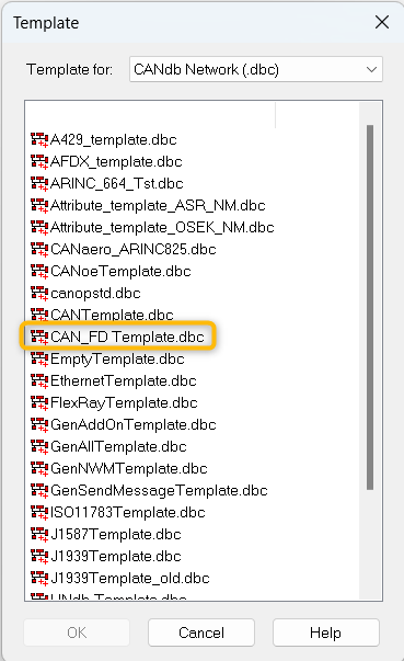
This will open the below window, where we need to choose the template for our file. As we discussed earlier, Vector offers a variety of templates, each aimed at a particular use case. For the demonstration purposes, I will choose a CAN FD template. You can choose the one you are interested in.
Choose a template
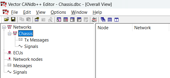
Now, the tool will ask you to save the file on your disk. Choose a suitable location and name your file and save it. Note, the file name that you choose will be the name of the network in the dbc file. This can also be changed later, so you can name your file as per your needs. Here, I have named it as “Chassis.dbc”, so my network name is also Chassis.
Network view
Create Nodes/ECUs
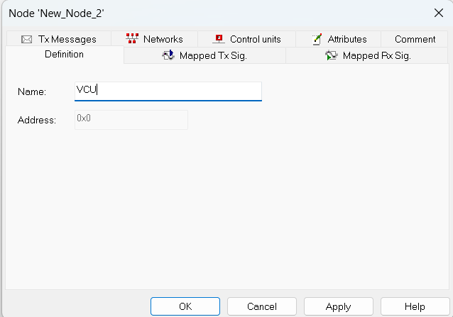
As you can see, an empty network is created. Next we need to add the ECUs which will be part of this network. Here, we will consider four ECUs namely, VCU, BrakeController, SteerController and BodyController. To add the ECUs, right click on “Network Nodes” section and select “New”. It opens a new dialog box as below.
Remove the default name and enter the required name.
Create a node
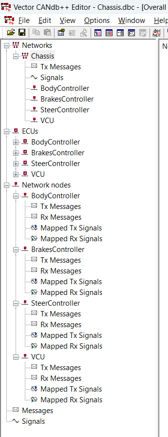
Similarly, add all the required nodes. Once all the nodes are added, we will be able to see them, as below
DBC view after adding the nodes
Create Messages
Next, we can add a message. For this, right click on “Messages” section and select “New”. You will see the below dialog box
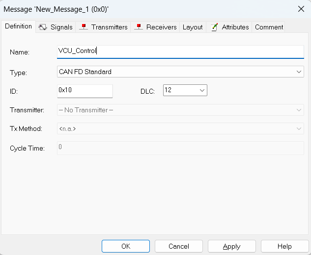
Create your message
Give a valid name, name should signify what the message is used for. If you have an organization level naming convention, you can use it.
Select the type of message that is, whether it is a Standard/Extended/FD CAN message.
Give an ID to your message, which will be the CAN ID.
Select the DLC.
Next, go to “Transmitters” tab and click on “Add”.
From the dialog box, select the node which should transmit this message, and click on OK.
Finally click on OK.
Now, you will see that the message is also added under the respective nodes Tx Messages list.
Similarly, you can create as many messages as you want.
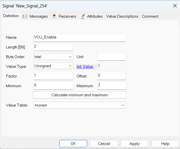
Next, lets create a Signal. For this, go to “Signals” section and right click. Select “New”.
You will see the below dialog box. Update the fields as per your need.
Add Signals
Signal creation
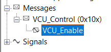
Next, to link this signal to the message which it will be part of, switch to “Messages” tab and click on Add. Select the required message. Then click on OK. You will see that this signal is added under the selected message.
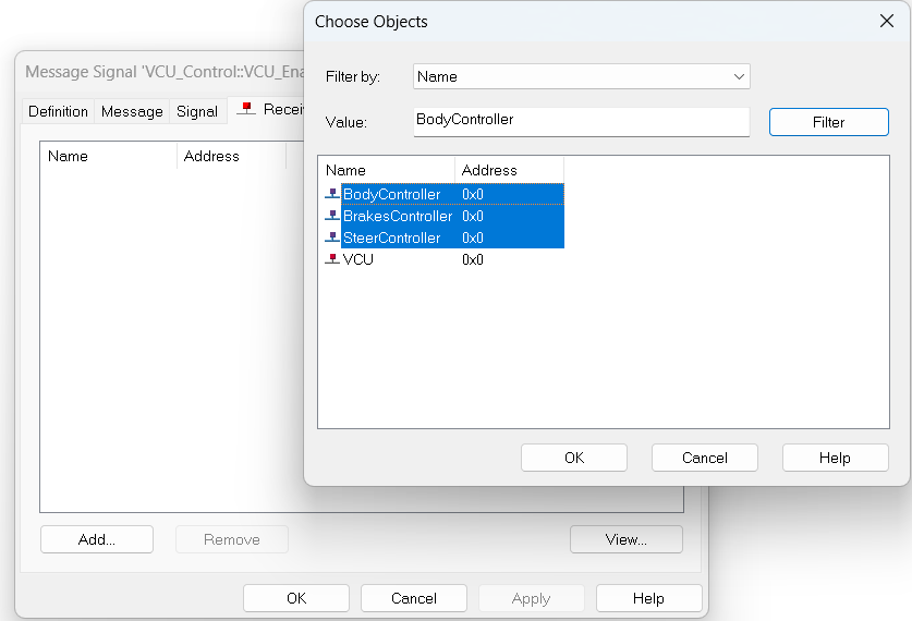
Now, to add the receivers for a particular signal, go to the required signal under the message and double click. It will open the signal properties dialog box. Goto “Receivers” tab and click on Add. Here you can select multiple nodes which will be receiving this signal.
After this, you can see that the message and signal both are added as part of “Rx Messages” of all the selected nodes.
Similarly, you can add all you messages and signals. Once done, you can save the file.
This is the process of creating a CAN DBC. There are some topics like Signal Properties, Value Tables, comments and others. If you want me to cover them, leave me a comment below. Also, if there is any other topic that you are interested in learning, let me know and I will try to cover it. Please share this tutorial with your friends and see you again.