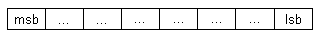
We know that a CAN message consists of 8 bytes. Each byte consists of 8 bits. Within each byte, the bit ordering is fixed as shown below, where lsb is the least significant bit and msb stands for most significant bit.
When the data is transmitted on the bus, low bits of the first byte is transmitted first and then the high bits. To visualize this lets take a look at the data transmission sequence
This looks pretty simple right? Then why do we have an option to select the byte order while configuring a signal? This can be understood by understanding how the receiving node reconstructs the received message. This involves receiving the message, once all the initial checks are done, for correct interpretation of the received information, it needs
- Signal start bit and length information
- The arrangement of the signal at Transmitter end(Byte-order).
If the Sender and receiver do not use the same byte order convention, the data can be mis-interpreted.
Now, there are two types of byte orders used in CAN communications.
- Intel or Little Endian Type
- Motorola or Big Endian Type
Intel Byte Order
In Intel type, Low byte is stored at low address, and high byte is stored at high address. Lets take an example to understand this. Lets say we have a 10 bit signal and is configured as Intel type.
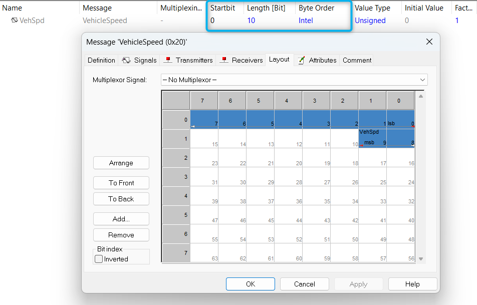
As we can see, the signal length is 10 bits and is of intel byte order. The start bit of the signal is 0th bit of 0th byte. When it is transmitted, first the 0th byte and next the 1st byte is transmitted. So when the receiver receives it, it has to reconstruct the signal as shown below
VehSpd = ( (Byte1 << 8) + Byte0 )
Now lets consider the same signal is configured to be a Motorola signal, as shown below
Motorola Byte Order
In Motorola Type, High byte is stored at low address, low byte is stored at high address. Lets change the above signal to Motorola type. As we can see, the start bit is now changed to 8. We can also see a red arrow beginning at the start bit and going all the way upto the last bit. the little white arrows show the continuation.
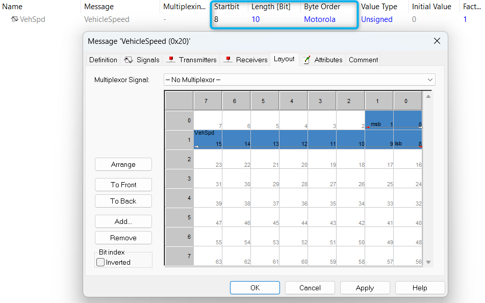
If the receiver wants to accurately reconstruct this signal, it has to do,
VehSpd = ( (Byte0 << 8) + Byte1 )
There is one more thing, if the signal length is less than or equal to 8 bits, it really doesnt matter if its of Intel type or Motorola type. It is only significant if the signal spans over two or more bytes as demonstrated.